Ferm 51
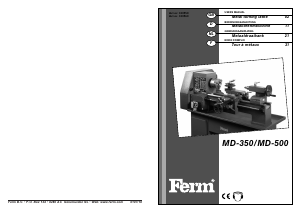
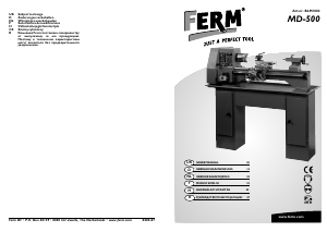
BENCH LATHE MD-350 / MD 500
CAREFULLY READ THE INSTRUCTIONS BEFORE
YOU USE THE BENCH LATHE!
Carefully read this manual before using the machine. Ma-
ke sure that you know how the machine functions and how
to operate it. Maintain the machine in accordance with the
instructions to make sure it functions properly. Keep this
manual and the enclosed documentation with the machi-
ne.
USE
The metal lathe has been designed for processing, me-
chanically removing metal, of ferrous and non-ferrous me-
tals, synthetics and wood. The metal lathe is meant for se-
mi-professional use and for leisure interests.
SAFETY INSTRUCTIONS
When using electric machines always observe the
safety regulations applicable in your country to redu-
ce the risk of fire, electric shock and personal injury.
Read the following safety instructions and also the
enclosed safety instructions.
Keep these instructions in a safe place!
At the design of the machine is made allowance for the re-
quirements for a safe use. Every change, adaptation, re-
construction or other adaptation use can cancel the safety
of the object. Besides the guarantee will expire through
this.
Before, after and during working with the lathe a number of
safety rules have to be taken. By the presence of turning
parts and sharp objects very severe injury can arise. Espe-
cially the bits of the turning chuck are very dangerous.
1. The lathe has been designed for manufacturing unruly
material and so it has to be able to develop a lot of po-
wer.
That is why touching turning parts is perilous. For this
reason unlawfully, undesirably or unintentionally swit-
ching on the machine has to be prevented, for example
by the pushed in locking of the emergency stop valve
by means of a small padlock.
2. By the elastic working of the chisel metal parts can
be shoot away with a big power at the most unex-
pected moments.
- Protection of the eyes is very important. Make it a habit
to wear special safety glasses when you are in the
space where the lathe stands. Buy yourself a profes-
sional and tested copy which you can wear for a long ti-
me and if need be for visitors a cheaper one, but this
one also has to be a good performance.
- If you take care of a cheerful workshop you can prevent
for example gripping in the machine or falling by stum-
bling over flinging about material.
3. Be very careful when you make turning pieces of
work with the hands.
- When you want to polish a surface turning, then take a
long piece of polish paper which you can place half
around the piece of work, with the ends to your direc-
tion.
- Never turn the ends around the fingers, never push
sand-paper on the piece of work with your hands.
- By turning, edges of the piece of work exist which are
sharp as a razor. These edges have to be smoothed off
with a file or a trimming hook.
4. Never remove chipcurls with your hands
Use a little hook which has been made by yourself of
thread or buy a professional chips hook.
5. Never grip over the turning machine or chuck
when during turning something falls in or behind
the bed.
Always first stop the machine. See that the covering
plate lies on the opening in the bed.
6. A good lighting prevents that you operate the ma-
chine from too close by.
- If you apply strip light you have to make allowance for
the so-called strobosto scopic effect. Through this a
turning object seems to stand still. A solution is the use
of double armatures by which a phase shifting of the
two strip lights has been accomplished.
7. Emergency stop
If a dangerous situation arises unexpectedly, for exa-
mple if a badly exerted piece of work seems to get loo-
se during turning, you van use the emergency stop by
giving a tap on the yellow cover of the safety switch,
marked “STOP”. The machine now stops without pus-
hing in the switch button yourself.
2 Ferm
SPARE PARTS FOR MD-350/MD-500
REF. NR. DESCRIPTION FERM NR.
0.01 Shears 400311
0.02 Intermediate gear spindle 400312
1.01 Locking handle 400300
1.03 Clamping nut 400301
1.05 Spindle 400302
1.06 Spindle bearing 400303
1.07 Handwheel for support 400304
1.08 Cover plate 400305
1.09 Spindle nut 400306
1.10 Tail stock 400307
1.11 Pinole MT-2 400308
1.12 Baseplate / bedplate 400309
1.13 Locking bolt 400310
2.02 Press handle 400313
2.03 Holder complete 400314
2.04 Axle pin tool holder 400315
2.05 Tool support (top) 400316
2.06 Sunk key 400317
2.09 Spindle 400318
2.14 Handle 400319
2.16 Nut (tool slide) 400320
2.17 Tool slide (under) 400321
2.18 Locking bolt 400322
2.20 Turning pin 400323
2.21 Key cross slide 400324
3.01 Handle 400325
3.04 Spindle 400326
3.05 Spindle nut 400327
3.10 Baseplate cross slide 400328
3.11 Hollow key 400329
3.13 Longidutinal direction spindle 400330
3.15 Hand wheel 400331
3.17 Half nut lever 400332
3.18 Half nut mechanism 400333
3.21 Longiditunal direction spindle (internal) 400334
3.22 Bearing 400335
4.03 Motor 400336
4.04 Motor pulley 400337
4.07 Headstock with cover 400338
4.08 Main spindle 400339
4.10 Main spindle pulley 400340
4.11 Intermediate pulley 400341
4.12 Tension roller 400342
4.16 Switch 400343
4.17 Bearing (lead screw) 400344
4.23 Thrust bearing 400345
4.24 Rack MD-350 400346
4.24 Rack MD-500 400367
4.24 Rack 400366
5.01 Gear 51 400347
5.02 Gear 68 400348
5.03 Gear 25 400349
5.04 Gear 75 400350
5.05 Gear 76 400351
5.06 Gear 24 400352
5.07 Gear 24 400353
5.08 Gear 76 400354
5.09 Gear 56 400355
5.10 Gear 56 400356
5.11 Change wheel 30 400357
5.12 Change wheel 42 400358
5.13 Change wheel 49 400359
5.14 Change wheel 28 400360
5.15 Change wheel 63 400361
5.16 Change wheel 70 400362
5.17 Change wheel 84 400363
5.18 Change wheel 98 400364
5.19 Change wheel 105 400365
- Center MC-3 400368
- Center MC-2 400369
- 3-Jaw chuck 400370
- 4-Jaw chuck 400371
- V-belt tension roller 400372
- Micro switch for door 400373
- V-Belt Z31 (10 x 790) 800114
- V-Belt Z28 (10 x 710) 800170
- V-Belt Z35 (10 x 890) 800197
- The reference numbers refer to the 5 annexes indicated
with the numbers 0, 1, 2, 3, 4, 5.
The number in front of the point refers to the Annex, the
number behind the point refers to the part.
So, reference 4.07 refers to Annex 4, part 7
- Die Referentienummer referieren auf 5 Beilage die Mittels
den Nummern 0, 1, 2, 3, 4 und 5 angegeben werden.
Die Nummer vor dem Punckt verweißt auf die Beilage, die
Nummer hinter dem Punckt auf das Unterteil. So die Ver-
weißung 4.07 referiert auf Beilage 4, Unterteil 7.
- De Referentienummers verwijzen naar de 5 bijlagen aan-
gegeven met de nummers 0, 1, 2, 3, 4 en 5.
Het nummer voor de punt verwijst naar de bijlage, het num-
mer achter de punt naar het onderdeel
Referentie 4.07 verwijst dus naar bijlage 4, onderdeel 7.
- Les numéros de reference se référent à les 5 annexes, indi-
quées avec les numéros 0, 1 ,2 ,3, 4 et 5. Le numéro devant
le point se réfère à l’annexe, le numéro à derrière le point se
réfère à la pièce détachée. Par conséquant la référence
4.07 se réfère à annexe n°4, pièce détachée n°7.


Joignez-vous à la conversation sur ce produit
Ici, vous pouvez partager ce que vous pensez du FERM BLM1001 Tour. Si vous avez une question, lisez d’abord attentivement le mode d’emploi. La demande d’un mode d’emploi peut être effectuée en utilisant notre formulaire de contact.
répondre | Cela a été utile (0)