Ferm 3
13. Never atempt to remount a faceplate turning to the
faceplate for any reason. Never attempt to remount a
between-centres turning if the original centres in the
turning have been altered or removed. Be positive
the lathe is set at the lowest speed if remounting a be-
tween-centres turning with non-altered original
centres.
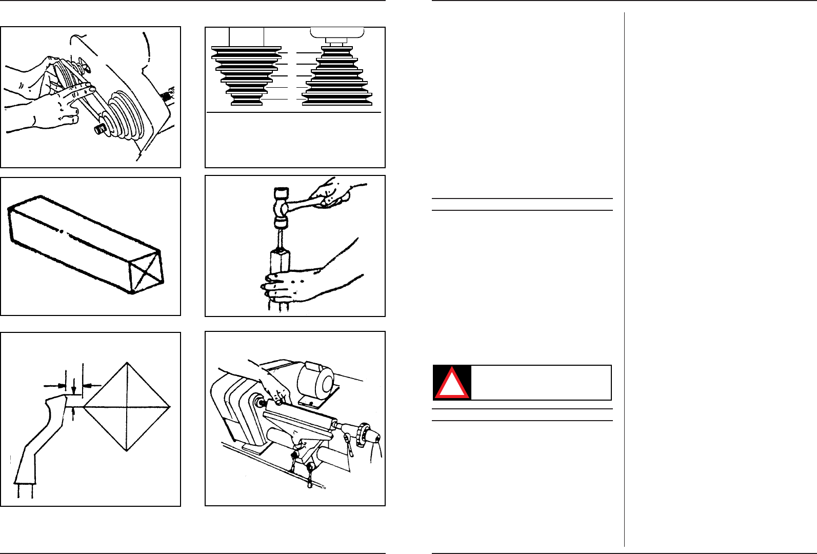
14. Use extra caution in mounting a between-centres or
spindle turning to the faceplate, or a faceplate turning to
between centres, for subsequent operation. Be positive
the lathe is set at lowest speed for turning on.
15. Never mount a workpiece that contains any splits,
cracks or knots to a faceplate or between-centres.
IMMEDIATELY SWITCH OFF THE MACHINE
IN CASE OF:
1. Malfunction of the mainsplug, -socket or damaged ca-
bles.
2. Broken switch.
3. Smoke or smell caused by scorched insulation.
3. UNPACKING
(Fig. 1.).
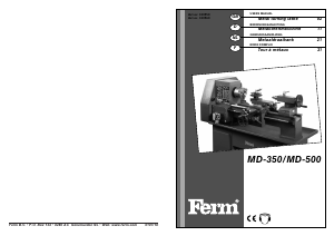
-Head stock assembly. includes: Head stock, drive
spindle, motor, drive belt, pulleys (2), pulley guard, in-
dexing head, 3/4” - 16 nut, no volt release switch, po-
wer cord, outboard spindle cover.
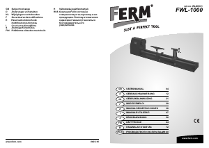
- Bed, (B1 = Head stock End, B2 = Foot End)
- Foot
- Bed clamping bolt
-Tail stock assembly
- Tool rest bracket
- Tool rest base assembly
- Centre assembly - tail stock
- Spur centre - head stock
- Tool rest - 300 mm
- Tool rest - 150 mm
-2 Faceplates - 110 mm. (IN + OUT)
Never use gasoline or similar highly volatile
solvents. Apply a coat of automobile wax to
the bed. Wipe all parts thoroughly with a
clean dry cloth.
4. ASSEMBLY AND INSTALLATION
1. MOUNTING HEAD STOCK TO BENCH
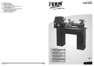
1. Drill two 10 mm holes in your bench or stand accor-
ding to diagram, Fig.2.
Note: Make sure that the top of your bench is posi-
tioned so that you don’t drill into the legs or rail un-
derneath.
2. Position the head stock assembly (A) on the bench
and insert two 8 mm x 50 mm carriage bolts. through
the two mounting holes in the base. Place a flat was-
her, a lock washer and a nut from the underside on
each bolt. Tighten nuts only finger tight at this time.
2. ASSEMBLY OF LATHE BED HALVES (Fig.1)
1. Assemble the two bed halves together by inserting
the connecting end (plugged end with threaded hole
in the centre of the plug) of the head stock half (B1)
into the machined inside diameter of the tail stock
end (B2).
2. Insert the foot (E) into the open exposed end of the
tail stock half (B2) and now insert the bed clamping
bolt (F) through the foot (E) and on through the bed
half (B2) and into the threaded hole in the connector
end of the head stock bed half (B1). Start the threads
of the bolt (F) into the threaded hole but do not tigh-
ten at this time.
3. Align the two keys (the strips of metal bar fastened to
each bed half with screws) to be exactly in Iine. (This
alignment is necessary so that the Tail Stock Assem-
bly (G) and the Tool Rest Base Assembly (i) will slide
freely over the joint formed by B1 and B2). To do this
alignment, first align the two keys by ”eye” as close as
possible. Next using a metal straight edge against one
side of the keys, slide the end of the straight edge
across the joint first from one side of the joint and
then from the opposite side. lf there is a “click” or a
hang - up of the straight edge at the joint, it will be ob-
vious what relative direction the two halves of the
bed will have to be rotated to achieve alignment.
Repeat this process as many times on both sides of
the keys as necessary to be satisfied that the align-
ment has been attained.
4. Without changing the relative position of the two hal-
ves (B1 and B2) tighten bolt (F) with a wrench. Re-
check keyway alignment and if necesscary readjust.
Recheck halves of the bed (B1 and B2) can now be alig-
ned by repeating step 2C as is necessary. Also, before
retightening the foot (E) should be positioned so the
keyway on the bed will be facing straight down when
the foot is bolted to the bench.
5. Recheck key alignment and if necessary readjust per
paragraph 2C above after loosening and tightening of
the Bed Clamping Bolt Tighten the Bed Clamping Bolt
(F) after each alignment attempt always keeping the
Foot (E) parallel to key. Repeat above adjustment as
many times as necessary until key alignment and
squareness of the foot base (E) are obtained.
3. ASSEMBLY OF BED TO HEAD STOCK
1. Slide the tail stock assembly (G) cnd the tool rest base
assembly (H) on to the bed as shown in Fig. 3.
2. Now insert this bed assembly into the head stock as-
sembly (A), refer to Fig. 1, until the end of the tube is
flush with the outboard end of the head stock boss lo-
cated under the pulley cover.
3. Position the lathe on the bench so that the bed (B1
and B2) is parallel to the front edge of the bench.
4. Position the bed (B1 ond B2) in the Head Stock As-
sembly so that the key(s) are directly under the cent-
re of the bed towards the bench. Tighten the set
screw in the Head Stock Iocated on the motor side in-
line with the centre line of the bed.


Joignez-vous à la conversation sur ce produit
Ici, vous pouvez partager ce que vous pensez du FERM WLM1002 Tour. Si vous avez une question, lisez d’abord attentivement le mode d’emploi. La demande d’un mode d’emploi peut être effectuée en utilisant notre formulaire de contact.