DESCRIZIONE PRODOTTO E SPECIFICHE TECNICHE PRODUCT DESCRIPTION AND TECHNICAL SPECIFICATIONS
INSTALLAZIONE E COLLEGAMENTI
DESCRIZIONE COMANDI E FUNZIONAMENTO
IT
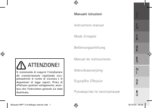
ATTENZIONE! Si raccomanda di eseguire l’installazione del dispositivo rispettando
scrupolosamente le norme di sicurezza e le disposizioni di legge vigenti. Prima di effettuare
qualsiasi collegamento, accertarsi che l’interruttore generale sia stato disattivato.
Questo dispositivo è un cronotermostato con controllo elettronico della temperatura ed orologio
elettromeccanico giornaliero. Realizzato in conformità con le direttive CE applicabili, secondo le norme
EN 60730-2-9, EN 60730-2-7, è interamente fabbricato in Italia.
Alimentazione: Batterie Alcaline 2x1,5V LR6 (Tipo AA)
Durata batterie: > 1 anno
Portata massima contatti: 5A(1A) 250VAC
Tipo di azione: 1B
Classe ErP I (+1%) - 811/2013 (regolazione ON/OFF)
Classe ErP IV (+2%) - 811/2013 (regolazione TPI)
Temperatura ambiente: 0°C ÷ 50°C
Campo di regolazione temperatura COMFORT: 10°C÷30°C
Campo di regolazione temperatura RIDOTTA: 10°C÷26°C
Differenziale temperatura (regolazione ON/OFF): 0,5K
Installare il dispositivo lontano da fonti di calore e correnti d’aria, a circa 1,5m dal pavimento.
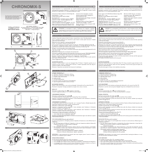
Aprire il dispositivo agendo con un cacciavite sui ganci laterali a sinistra quindi rimuovere il frontale
separandolo dalla base (Fig.2).
Rimuovere la vite e sganciare il coprimorsetto (Fig.3 A).
Infilare i cavi attraverso l’apertura sul fondo (Fig.3 C).
Fissare la base alla parete o sulla scatola incasso con delle viti, utilizzando gli appositi fori (Fig.3 B).
Per agevolare i collegamenti elettrici, estrarre la morsettiera a 3 vie (Fig.3 D), facendo una piccola
pressione verso l’esterno sulla levetta che tiene fissata la morsettiera alla base (Fig.3 E).
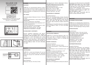
Collegare i cavi alla morsettiera come indicato (Fig.4).
Dopo avere collegato i cavi, inserire la morsettiera nella propria sede premendola delicatamente fino allo
scatto della levetta.
Riposizionare il coprimorsetto riavvitandolo alla base (Fig.3 A).
Selezionare la modalità di regolazione della temperatura, come descritto al capitolo “TIPO DI REGOLAZIONE”.
Inserire le batterie nell’apposita sede all’interno del frontale rispettando la polarità (Fig.5).
Rimettere il frontale sulla base, inclinandolo a 45° ed agganciare i dentelli (Fig.6).
Richiudere il dispositivo, allineando i contatti con la morsettiera sulla base, finché la parte superiore
tocca i ganci di blocco (Fig.7 A).
Premere leggermente per agevolare l’incastro delle due parti.
SOSTITUZIONE BATTERIE
Sostituire le batterie quando la spia rossa lampeggia (Fig.1 G). Aprire il dispositivo agendo con un
cacciavite sui ganci laterali a sinistra quindi rimuovere il frontale separandolo dalla base (Fig.2) e
sostituire le batterie come indicato (Fig.5).
Richiudere il dispositivo come indicato nelle istruzioni di installazione.
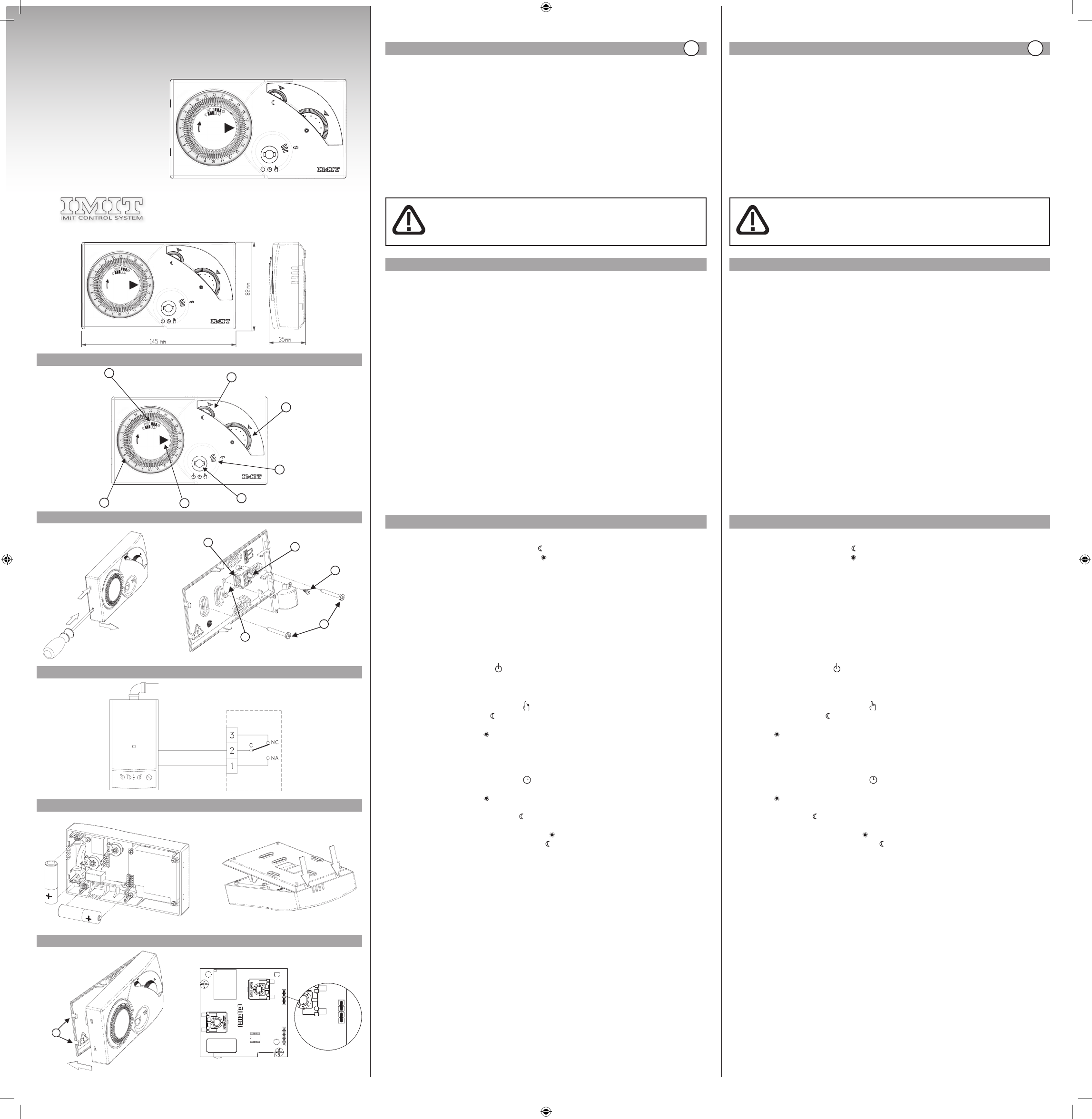
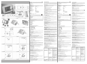
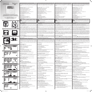
LEGENDA COMANDI (Fig.1)
A = Manopola impostazione temperatura ridotta
B = Manopola impostazione temperatura comfort
C = Selettore modo funzionamento
D = Indice orario ►
E = Orologio programmatore
F = Posizione selettori per temperatura Comfort/Ridotta
G = Spia di segnalazione batterie scariche ed allarmi
REGOLAZIONE OROLOGIO
Ruotare il disco dell’orologio in senso orario posizionando l’indicatore ► sull’ora attuale (Fig.1 D).
Ricordare di reimpostare l’orologio passando da ora legale ad ora solare e viceversa.
MODO OFF
Posizionare il selettore (Fig.1 C) su
per spegnere il termostato.
In caso di temperatura ambiente < 5°C si attiva la funzione antigelo.
FUNZIONAMENTO MANUALE
Posizionare il selettore (Fig.1 C) sul simbolo
.
La manopola temperatura ridotta (Fig.1 A) e l’orologio (Fig.1 E) sono disabilitati.
Impostare la temperatura desiderata: posizionare il valore desiderato sotto l’indicatore di riferimento
ruotando la manopola Comfort (Fig.1 B).
FUNZIONAMENTO AUTOMATICO
La temperatura regolata nell’ambiente (impostata con le manopole Comfort o Ridotta) dipende dalle
impostazioni effettuate sull’orologio e cambia automaticamente.
Posizionare il selettore (Fig.1 C) sul simbolo
.
Impostare la temperatura comfort: posizionare il valore desiderato sotto l’indicatore di riferimento
ruotando la manopola Comfort (Fig.1 B).
Impostare la temperatura ridotta: posizionare il valore desiderato sotto l’indicatore di riferimento
ruotando la manopola temperatura ridotta (Fig.1 A).
Programmare l’orologio posizionando le levette (Fig.1 F):
• verso l’esterno per avere la temperatura comfort ;
• verso il centro per avere la temperatura ridotta .
Verificare che l’indice dell’orologio indichi l’ora attuale ed eventualmente agire come indicato al capitolo
“REGOLAZIONE OROLOGIO”.
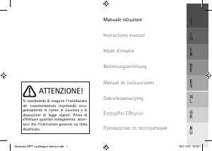
TIPO DI REGOLAZIONE (Riservato agli installatori)
La posizione dei ponticelli A e B (Fig.8), permette al dispositivo di funzionare con due differenti tipi di
regolazione:
• ON / OFF (impostazione di fabbrica): Il dispositivo si attiva con temperatura ambiente inferiore alla
temperatura impostata e si spegne quando la raggiunge.
A=Presente, B= Presente
• TPI: Il dispositivo si attiva con temperatura ambiente inferiore a quella impostata e, avvicinandosi
alla temperature richiesta, riduce i periodi di funzionamento della caldaia ottimizzando il comfort
ambientale e riducendo sensibilmente i consumi.
A=Assente, B=Presente (ottimizzato per impianti a radiatori)
A=Assente, B=Assente (ottimizzato per impianti a pavimento)
IMPORTANTE: il riposisizionamento dei ponticelli deve essere eseguito prima di inserire le batterie o
comunque con il dispositivo privo di batterie.
SEGNALAZIONE ANOMALIE
La spia rossa del dispositivo (Fig.1 G) si attiva per segnalare:
• con 2 lampeggi lenti: batterie quasi scariche. Sostituirle al più presto.
• con 2 lampeggi veloci: batterie esaurite. Sostituirle per ripristinare il funzionamento del dispositivo.
• con lampeggio veloce continuo: anomalia interna del dispositivo. Sostituire le batterie e verificare le
condizioni ambientali di funzionamento prima di sostituire il dispositivo.
This device is a chronothermostat with electronic temperature control and daily electromechanical clock.
Produced in accordance with the applicable EC directives, according to the standards EN 60730-2-9,
EN 60730-2-7, it is entirely manufactured in Italy.
Power supply: 2x1.5V LR6 Alkaline Batteries (Type AA)
Battery life: > 1 year
Maximum contact capacity: 5A(1A) 250VAC
Action type: 1B
ErP class I (+1%) - 811/2013 (ON/OFF regulation)
ErP class IV (+2%) - 811/2013 (TPI regulation)
Operating Temperature: 0°C ÷ 50°C
COMFORT temperature regulation range: 10°C÷30°C
REDUCED temperature regulation range: 10°C÷26°C
Temperature differential (ON/OFF regulation): 0.5K
Install the device away from heat sources and and drafts, about 1.5m from the floor.
Using a screwdriver open the device via the side hooks on the left and then remove the front, separating
it from the base (Fig.2).
Remove the screw and detach the terminal cover (Fig.3 A).
Insert the cables through the opening on the bottom (Fig.3 C).
Attach the base to the wall or on the flush mounted box with screws, using the relevant holes (Fig.3 B).
To facilitate the electrical connections, remove the 3-way terminal block (Fig.3 D), exerting slight
outward pressure on the lever that secures the terminal block to the base (Fig.3 E).
Connect the wires to the terminal block as indicated (Fig.4).
After connecting the cables, insert the terminal block into place, pressing it gently until the lever clicks.
Replace the terminal cover, screwing it back onto the base (Fig.3 A).
Select the temperature regulation mode, as described in the chapter “REGULATION TYPE”.
Insert the batteries into the slot inside the front ensuring correct polarity (Fig.5).
Refit the front onto the base, tilting it 45° and engage the notches (Fig.6).
Close the device again, aligning the contacts with the terminal block on the base until the upper part
touches the lock hooks (Fig.7 A) .
Press lightly to facilitate connection of the two parts.
BATTERY REPLACEMENT
Replace the batteries when the red light flashes (Fig.1 G) . Using a screwdriver open the device via the
side hooks on the left and then remove the front, separating it from the base (Fig.2) and replace the
batteries as indicated (Fig.5).
Close the device again as shown in the installation instructions.
COMMANDS LEGEND (Fig.1)
A = Reduced temperature setting knob
B = Comfort temperature setting knob
C = Operating mode selector
D = Timer index ►
E = Programmer clock
F = Position of selectors for Comfort/Reduced temperature
G = Light for low battery warning and alarms
CLOCK ADJUSTMENT
Rotate the disc of the clock clockwise positioning the indicator ► on the current time (Fig.1 D).
Remember to reset the clock moving from Daylight Saving Time to Standard Time and vice versa.
OFF MODE
Position the selector (Fig.1 C) on
to turn off the thermostat.
In case of ambient temperature < 5°C the anti-freeze function is activated.
MANUAL OPERATION
Position the selector (Fig.1 C) on the symbol
.
The reduced temperature knob (Fig.1 A) and the clock (Fig.1 E) are disabled.
Set the desired temperature: position the desired value under the reference indicator by turning the
Comfort knob (Fig.1 B).
AUTOMATIC OPERATION
The temperature regulated in the environment (set with the Comfort or Reduced knobs) depends on the
settings chosen on the clock and changes automatically.
Position the selector (Fig.1 C) on the symbol
.
Set the comfort temperature: position the desired value under the reference indicator by turning the
Comfort knob (Fig.1 B).
Set the reduced temperature: position the desired value under the reference indicator by turning the
reduced temperature knob (Fig.1 A).
Program the clock by positioning the levers (Fig.1 F):
• outwards for the comfort temperature ;
• towards the centre for reduced temperature .
Check that the index of the clock shows the current time and if necessary proceed as indicated in chapter
“CLOCK ADJUSTMENT”.
REGULATION TYPE (Reserved for installers)
The position of the jumpers A and B (Fig.8) allows the device to work with two different types of
temperature regulation:
• ON / OFF (factory setting): The device is activated when the ambient temperature is lower than the
temperature set and turns off when it reaches the temperature set.
A=Present, B= Present
• TPI: The device is activated when the ambient temperature is lower than the temperature set and,
approaching the required temperature, reduces the operating periods of the boiler, optimising
environmental comfort and reducing energy consumption.
A=Absent, B=Present (optimised for radiator systems)
A=Absent, B=Absent (optimised for floor systems)
IMPORTANT: repositioning of the jumpers must be performed before inserting the batteries or in any
case with the device with batteries removed.
FAULT INDICATION
The red light of the device (Fig.1 G) is activated to indicate:
• with 2 slow flashes: batteries almost flat. Replace them as soon as possible.
• with 2 quick flashes: batteries flat. Replace them to restore functioning of the device.
• with continuous quick flashing: fault inside the device. Replace the batteries and check the operating
environment conditions before replacing the device.
Intervallo minimo impostabile: 15 minuti
Sonda di temperatura: NTC 100KΩ@25°C
Grado di protezione: IP20
Classe di isolamento: Tipo II (doppio isolamento)
Grado d’inquinamento: 2
Software: classe A
Resistenza al calore ed al fuoco: Categoria D
Temperatura di stoccaggio: -25÷60°C
Tensione nominale di tenuta ad impulso: 2,5kV
Montaggio: a parete
Minimum settable interval : 15 minutes
Temperature sensor: NTC 100KΩ@25°C
Degree of protection: IP20
Insulation class: Type II (double insulation)
Pollution degree: 2
Software: class A
Resistance to heat and fire: Category D
Storage temperature: -25÷60°C
Rated impulse withstand voltage: 2.5kV
Mounting: wall
WARNING! It is recommended to install the device in strict accordance with the safety
regulations and laws in force. Before making any connection, make sure that the main
switch is off.
INSTALLATION AND CONNECTIONS
DESCRIPTION OF COMMANDS AND OPERATION
EN
Fig. 1
1
6
1
8
2
0
2
2
24
1
8
1
6
1
8
2
0
2
2
24
1
8
A
B
C
D
E
F
G
A
D
E
A
B
C
Fig. 2 Fig. 3
Fig. 4
A
B
Fig. 5
Fig. 6
Fig. 7
Fig. 8
IMIT CONTROL SYSTEM s.r.l.
Via Varallo Pombia,19 - Castelletto Sopra Ticino (NO)
Tel (+39)0331941600 - Fax (+39)0331973100
Cronotermostato elettronico giornaliero
Daily electronic chronothermostat
Chronothermostat electronique journalier
Cronotermostato electronico diario
1
6
1
8
2
0
2
2
24
1
8
077619 Rev0217
CHRONOMIX-S
Manuale_Chronomix-S_multilingue_390x400.indd 1 03/02/17 14:16


Joignez-vous à la conversation sur ce produit
Ici, vous pouvez partager ce que vous pensez du IMIT 578180 Chronomix-S Thermostat. Si vous avez une question, lisez d’abord attentivement le mode d’emploi. La demande d’un mode d’emploi peut être effectuée en utilisant notre formulaire de contact.
répondre | Cela a été utile (1) (Traduit par google)
répondre | Cela a été utile (0) (Traduit par google)