4
5
Only use accessories specically
recommended for this tool. Others
may be hazardous.
Use only sockets and other accessories speci-
cally designed for use on impact wrenches. Other
sockets and accessories might shatter or break
causing injury.
Attaching and Removing Accessories
1/2" Impact Wrench with Pin Detent
(Cat. No. 2966-20)
1. WARNING! Remove battery to avoid starting the tool.
2. Use only the appropriate size Square Drive Sockets.
3. To attach a socket, align the hole in the accessory
with the detent pin on the anvil. Hold the detent
pin in while pushing the socket onto the anvil.
The detent pin will snap into place in the hole to
secure the socket.
4. To remove the socket, insert a nail or other thin
object into the hole in the accessory and press
in the detent pin. Pull the accessory o the anvil.
1/2" Impact Wrench with Friction Ring
(Cat. No. 2967-20)
1. WARNING! Remove battery to avoid starting the tool.
2. Use only the appropriate size Square Drive Sockets.
3. To attach a socket, align the accessory with the
anvil and push it rmly over the retaining ring.
4. To remove the accessory, pull the accessory o
the anvil.
OPERATION
To reduce the risk of injury, always
wear proper eye protection marked
to comply with ANSI Z87.1.
Using the Drive Control
The drive control button is used to adjust the torque,
rotation speed (RPM), and impact speed (IPM) for
the application.
To select the drive control mode:
Drive Control Button
Mode Indicator
1. Pull and release the trigger
to turn on the tool. The cur-
rent mode indicator is lit.
2. Press the drive control but-
ton to cycle through the
4 modes. When the desired
mode indicator is lit, begin
work.
Cat. No. 2966-20
Mode RPM IPM
Fastening
Torque
(ft-lbs)
Nut-Busting
Torque
(ft-lbs)
1 0 - 700 0 - 1400 Up to 350* Up to 350*
2 0 - 1300 0 - 2500 Up to 750* Up to 750*
3 0 - 2000 0 - 2700 Up to 900* Up to 1100*
FWD:
0 - 900
REV:
0 - 2000 /
0 - 750
0 - 2700 Up to 50*
†
Up to 1100*
Cat. No. 2967-20
Mode RPM IPM
Fastening
Torque
(ft-lbs)
Nut-Busting
Torque
(ft-lbs)
1 0 - 700 0 - 1300 Up to 650* Up to 650*
2 0 - 1300 0 - 2200 Up to 900* Up to 900*
3 0 - 2000 0 - 2400
Up to 1100
w/ XC5.0Ah
battery*
Up to 1200
w/ FORGE™
battery*
Up to 1500
w/ XC5.0Ah
battery*
Up to 1600
w/ FORGE™
battery*
FWD:
0 - 900
REV:
0 - 2000 /
0 - 750
0 - 2400 Up to 50*
†
Up to 1500
w/ XC5.0Ah
battery*
Up to 1600
w/ FORGE™
battery*
*Torque values depend on many factors such as state
of battery discharge, battery size, impacting time, bolt
size, etc. Always check with a torque wrench to ensure
desired torque value is achieved. This is not a precision
fastening tool.
†
Auto Shut-O Mode
In mode, when run in reverse, the tool will spin
at the above RPM and IPM until the nut breaks free
from the joint. Then, the tool slows to 750 RPM for
better control in removing the nut.
Using the Control Switch
The control switch may be set to three positions:
forward, reverse and lock. Due to a lockout mecha-
nism, the control switch can only be adjusted when
the ON/OFF switch is not pressed. Always allow the
motor to come to a complete stop before using the
control switch.
For forward (clockwise) rotation, push in the control
switch from the right side of the tool. Check the
direction of rotation before use.
For reverse (counterclockwise) rotation, push in the
control switch from the left side of the tool. Check
direction of rotation before use.
To lock the trigger, push the control switch to the
center position. The trigger will not work while the
control switch is in the center locked position. Always
lock the trigger or remove the battery pack before
performing maintenance, changing accessories,
storing the tool and any time the tool is not in use.
Starting, Stopping and Controlling Speed
1. To start the tool, grasp the handle(s) rmly and
pull the trigger.
NOTE: An LED is turned on when the trigger is
pulled and will go o shortly after the trigger is
released.
2. To vary the speed, increase or decrease the pres-
sure on the trigger. The further the trigger is pulled,
the greater the speed.
3. To stop the tool, release the trigger. Ensure the
tool has come to a complete stop before laying
the tool down.
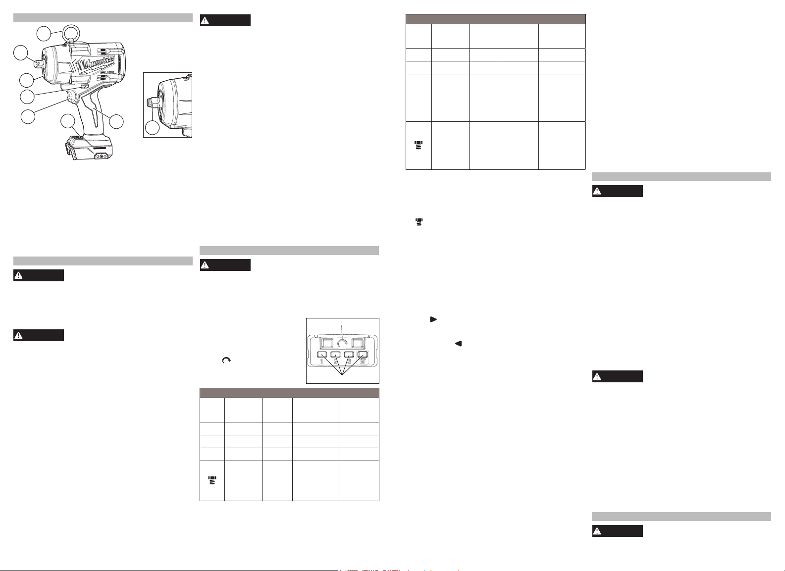
FUNCTIONAL DESCRIPTION
1. Tool hanger ring (2966-20 only)
2. Handle
3. Drive control
4. Trigger (ON/OFF switch)
5. Control switch
6. LED
7. 1/2" Square drive anvil with pin detent
(2966-20 only)
8. 1/2" Square drive anvil with friction ring
(2967-20 only)
7
5
3
6
4
8
2
1
ASSEMBLY
Recharge only with the charger
specied for the battery. For spe-
cic charging instructions, read the operator’s
manual supplied with your charger and battery.
Removing/Inserting the Battery
To remove the battery, push in the release buttons
and pull the battery pack away from the tool.
Always lock the trigger or remove
the battery pack any time the tool
is not in use.
To insert the battery, slide the pack into the body
of the tool. Make sure it latches securely into place.
Attaching and Removing the Tool Hanger
1. To attach, place the hanger ring through the tool
hanger.
2. Position the tool hanger on the tool over the two
screw holes.
3. Insert the two screws. Hand tighten the screws.
4. To remove, reverse the procedure.
Impacting Techniques
The longer a bolt, screw, or nut is impacted, the
tighter it will become. To help prevent damaging the
fasteners or workpieces, avoid excessive impact-
ing. Be particularly careful when impacting smaller
fasteners because they require less impacting to
reach optimum torque.
Practice with various fasteners, noting the length of
time required to reach the desired torque. Check the
tightness with a hand-torque wrench. If the fasteners
are too tight, reduce the impacting time. If they are
not tight enough, increase the impacting time.
Oil, dirt, rust or other matter on the threads or under the
head of the fastener aects the degree of tightness.
The torque required to loosen a fastener averages
75% to 80% of the tightening torque, depending on
the condition of the contacting surfaces.
On light gasket jobs, run each fastener down to a
relatively light torque and use a hand torque wrench
for nal tightening.
MAINTENANCE
To reduce the risk of injury, always
unplug the charger and remove the
battery pack from the charger or tool before
performing any maintenance. Never disassemble
the battery pack, charger, or tool, except as pro-
vided in these instructions. Contact a MILWAUKEE
service facility for all other repairs.
Maintaining Tool
Keep your tool, battery pack and charger in good
repair by adopting a regular maintenance program.
Inspect your tool for issues such as undue noise,
misalignment or binding of moving parts, breakage of
parts, or any other condition that may aect the tool
operation. Return the tool, battery pack, and charger
to a MILWAUKEE service facility for repair. After six
months to one year, depending on use, return the
tool, battery pack and charger to a MILWAUKEE
service facility for inspection.
If the tool does not start or operate at full power with
a fully charged battery pack, clean the contacts on
the battery pack. If the tool still does not work prop-
erly, return the tool, charger and battery pack, to a
MILWAUKEE service facility for repairs.
To reduce the risk of personal in-
jury and damage, never immerse
your tool, battery pack or charger in liquid or
allow a liquid to ow inside them.
Cleaning
Clean dust and debris from any vents. Keep tool
clean, dry and free of oil or grease. Use only mild
soap and a damp cloth to clean, since certain clean-
ing agents and solvents are harmful to plastics and
other insulated parts. Some of these include gasoline,
turpentine, lacquer thinner, paint thinner, chlorinated
cleaning solvents, ammonia and household deter-
gents containing ammonia. Never use ammable or
combustible solvents around tools.
Repairs
For repairs, return the tool, battery pack and charger
to the nearest authorized service center.
ACCESSORIES
Use only recommended accesso-
ries. Others may be hazardous.
For a complete listing of accessories, go online to
www.milwaukeetool.com or contact a distributor.

Joignez-vous à la conversation sur ce produit
Ici, vous pouvez partager ce que vous pensez du Milwaukee 2967-21B Visseuse à choc. Si vous avez une question, lisez d’abord attentivement le mode d’emploi. La demande d’un mode d’emploi peut être effectuée en utilisant notre formulaire de contact.