468 931 002 891-1
Bedienungsanleitung
Klimaregler mit Analogausgang
Typ 525 55 – Typ 525 56
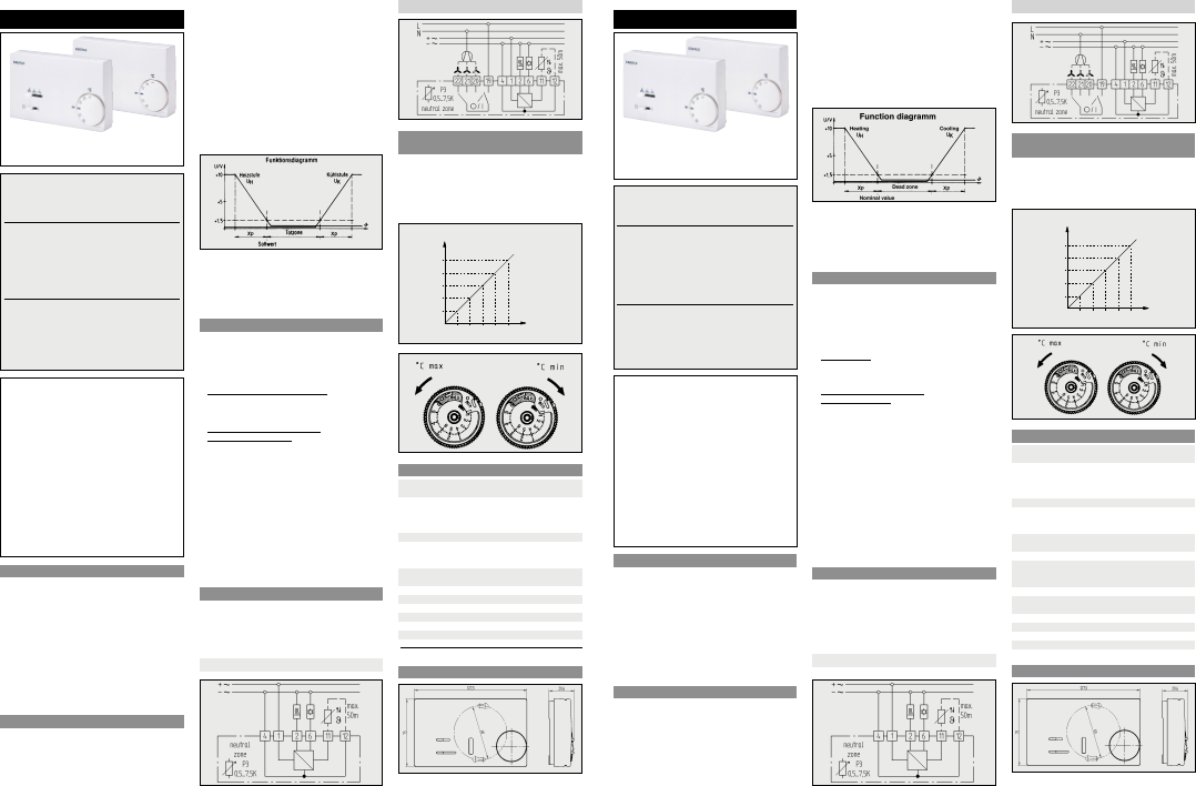
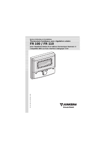
1. Verwendungsbereich
Der elektronische Klimaregler 525 55 ist für den Einsatz
in Klimaanlagen konzipiert, die die Raumtemperatur
über ein variables Volumensstromsystem regeln. Der
Regler 525 55 stellt dabei abhängig von der Raumtem-
peratur den Sollwert des Luftstromreglers ein. Außer-
dem besteht die Möglichkeit mit dem Regler 52555
Stellklappenmotore etc. direkt zu steuern.
Der elektronische Klimaregler 52556 wird zur Steue-
rung von Gebläsekonvektoren (Fan Coils) verwendet,
die mit stetig regelbaren Ventilen für Kalt- und/oder
Warmwasserzufluss ausgerüstet sind.
Zusätzlich besteht die Möglichkeit die Ventilatorge-
schwindigkeit mittels des eingebauten Schiebeschalters
zu regulieren.
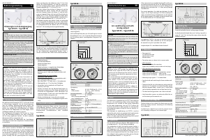
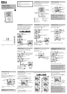
2. Funktionsbeschreibung
Siehe hierzu Anschluss-Schaltbild und Funktionsdia-
gramm. Beide Geräte besitzen je einen Analogausgang
0…10 V für Heizen und Kühlen. Mit dem Sollwert wird
die Temperatur eingestellt, bei der der Ausgang Heizen
einen Spannungswert von 1,5 V erreicht. Wenn die Tem-
peratur ansteigt, fällt der Spannungswert des Ausgangs
Hinweis: Das Gerät wird mit eingebautem Tempe-
raturfühler (NTC-Widerstand) ausgeliefert. Bei Be-
trieb mit Fernfühler (000 193 720 000) ist der in-
terne Fühler (R 15) zu entfernen und die Brücke Br1
aufzutrennen. Der Fernfühler ist an den Klemmen
11 und 12 anzuschliessen.
Das Fühlerkabel kann mit einem Querschnitt von
1,5 mm
2
bis auf 50 m verlängert werden, wenn ein
geschirmtes Kabel verwendet wird (Schirm an
Kl. 12). Die Fühlerkabel-Verlängerung einschliess-
lich Schirm muß im allgemeinen nach Schutzklasse
II gegen Berühren geschützt sein.
Nur wenn der Regler und beim Typ 525 56 auch die
Lüfterstromkreise an Schutzkleinspannung ange-
schlossen sind, ist kein Berührungsschutz erforder-
lich. In diesem Fall muß aber die Fühlerkabelver-
längerung einschliesslich Schirm gegen Spannun-
gen, die keine Schutzkleinspannungen sind, dop-
pelte oder verstärkte Isolierung haben.
Achtung!
Dieses Gerät darf nur durch einen Elektro-Fachmann
gemäß dem Schaltbild im Gehäusedeckel installiert wer-
den. Dabei sind die bestehenden Sicherheitsvorschriften
zu beachten.
Ö
wird durch entsprechenden Einbau (nach VDE 0100)
und der Montage auf einen ebenen, nichtleitenden
und nichtbrennbaren Untergrund erfüllt.
Dieser unabhängig montierbare Raumtemperaturregler
dient zur Regelung der Temperatur ausschließlich in troc-
kenen und geschlossenen Räumen mit üblicher Umge-
bung. Außerdem ist er gemäß VDE 0875 bzw. EN 55014
funkentstört undarbeitet nach der Wirkungsweise 1 Y.
Achtung bei Typ 525 56 !
Die Betriebsisolierung zwischen Lüfterstromkreis und den
anderen Stromkreisen ist nach VDE D531 Abschnitt 14.1
für eine Nennspannung 250 V ausgelegt. Wenn das Gerät
an Schutzkleinspannung angeschlossen werden soll, dann
müssen alle Stromkreise des Gerätes in Schutzkleinspan-
nung angeschlossen werden.
Heizen nach Erreichen des Sollwertes unter 1,5 V ab. Sinkt
danach die Fühlertemperatur, so steigt der Spannungs-
wert des Analogausganges Heizen nach Durchlaufen des
Proportinalbandes Xp = 1,5 K bis auf 10 V an.
Wenn der Sollwert überschritten ist (Heizen aus) und die
Fühlertemperatur weiter ansteigt, fällt der Spannungs-
wert des Ausgangs Heizen auf nahezu 0 V und die Span-
nung am Ausgang Kühlen stellt sich nach Durchlaufen der
Totzone auf 1,5 V ein. Steigt die Temperatur weiter, dann
steigt die Spannung des Ausgangs Kühlen nach Durchlau-
fen des Proportionalbandes Xp = 1,5 K bis auf 10 V an.
Die Totzone zwischen den beiden Stufen ist werksseitig
auf 2 K eingestellt (P3-Markierung auf 2 K). Nach Entfer-
nen des Gehäuseoberteiles kann mit dem Potentiometer
P3 (Leiterplattenmitte) die Totzone von 0,5 K (Anschlag
links) bis 7,5 K (Anschlag rechts) eingestellt werden.
Bei dem Gerät 525 56 kann mit dem Wippenschalter ein
Gebläse ein- bzw. ausgeschaltet werden. Im eingeschal-
teten Zustand kann mit dem dreistufigem Schiebeschal-
ter die Gebläsestufe umgeschaltet werden (links =
schnell). Verlacktes Poti P2 darf nicht verdreht werden!
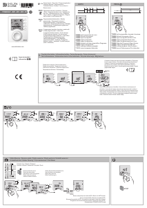
3. Montage
– Deckel entfernen;
Einstellknopf abziehen;
Deckelschrauben lösen
Deckel abziehen
– Deckel aufsetzen: in umgekehrter Reihenfolge
–W
andmontage ohne Unterputzdose:
Achten Sie auf eine ebene Montagefläche.
Befestigung mit 2 Holz- oder Blechschrauben und
Dübeln.
–W
andmontage auf Unterputzdose:
(DIN 49073) oder andere:
Nur mit Adapterrahmen, Befestigungslöcher wahl-
weise waagrecht oder senkrecht.
Best.-Bez. ARA 1,7-E Farbe: weiss + Schraubensatz
– Montagehöhe ca. 1,5 m über dem Fußboden.
– Vermeiden Sie Aussenwände und Zugluft von
Fenstern und Türen.
– Achten Sie darauf, dass die Raumluft den Regler un-
gehindert erreichen kann. Der Regler darf daher nicht
innerhalb von Regalwänden, hinter Vorhängen usw.
montiert werden. Er darf auch nicht direkt dem Luft-
strom des Gebläses ausgesetzt sein.
– Idealer Installationsort ist eine freie Innenwand.
– Fremdwärme beieinflusst die Regelgenauigkeit nach-
teilig.
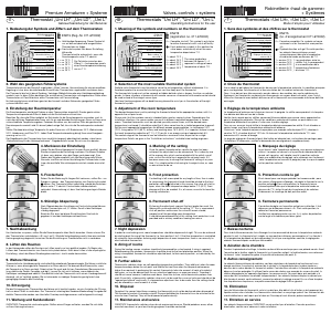
4. Anschluß-Schaltbild
Unbedingt technische Daten auf der Innenseite des
Gehäusedeckels beachten. Anschluss jeweils nach fol-
genden Schaltbildern vornehmen. Abisolierte Drähte in
entsprechende Schraubklemmen nach Schaltbild
anschließen.
Typ 525 55
Typ 525 56
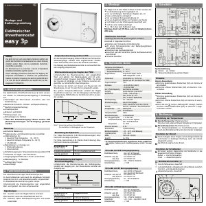
5. Einengung des
Temperatur-Einstellbereiches
Werkseitig ist der Regler auf den maximalen Einstellbe-
reich eingestellt.
Im Einstellknopf befinden sich 2 Einstellringe mit einem
Einstellbereich von 1 bis 6. Bei der Bereichseinengung
die Einstellung gemäß nachfolgendem Diagramm vor-
nehmen.
6. Technische Daten
Artikel-Nr. 515 7801 …
515 7811 …
Versorgung
Regler AC 24 V 50/60 Hz (20 … 30 V)
Lüfterschalter AC 24 V … 240 V 50/60 Hz
(20 … 264 V)
Leistungsaufnahme 0,35 W bei 24 V
Ausgänge 0 … 10 V DC
max. Ausgangsspannung13 V
max. Strombelastung 3 mA
Schalter für Gebläse (nur bei Typ 525 56)
Schaltstrom 6 (3) A
Temperaturbereich 5 … 30 °C
Totzone 2 K (0,5 … 7,5 K einstellbar*)
Proportionalband 1,5 K
Schutzart des Gehäuses IP 30 nach DIN 40 050
Geräteschutzklasse II
Lagertemperatur –25 … 70 °C
Betriebstemperatur –25 … 40 °C
*) nur durch verantwortlichen Installateur!
7. Maßzeichnung
Irrtum und Änderungen vorbehalten
468 931 002 891-1
Instructions for use
Air conditioning unit with
analog output
Type 525 55 – Type 525 56
1. Uses
The electronic air conditioning unit 525 55 was designed
for use in air conditioning systems which control room
temperature via a variable air flow system. Depending
on the room temperature, the unit 525 55 adjusts the
nominal value of the air flow regulator. It is also possible
to regulate the motors driving the fans etc. directly, us-
ing unit 52555.
The electronic air conditioning unit 525 56 is used to
control fan coils, which are equipped with continuously
adjustable fans for cold and/or warm water input.
There is a further possibility of controlling the fan speed
by means of the built-in slide switch.
2. Operation
See connection and circuit diagram. Both appliances have
an analog output 0 – 10 V for heating and cooling.
The temperature at which the heating output reaches a
voltage of 1.5 V is adjusted by the nominal value. When
the temperature rises, the voltage value of the heating
output falls after reaching the nominal value under 1.5 V.
If the sensor temperature then falls, the voltage value of
the analogue heating output rises after passing through
the proportional band X
P
= 1.5 K up to 10 V.
Note: The unit is supplied with an integrated tem-
perature sensor (NTC resistor). For operation with
remote sensor (type 000 193 217 000), the internal
sensor must be removed and the link Br1 severed.
The remote sensor should be connected to termi-
nals 11 and 12.
The sensor cable can be lengthened up to 50 m us-
ing a screened cable (screen to terminal 12) with
cross section 1.5 mm
2
. The sensor cable extension
including screen must be protected against acci-
dental contact in accordance with the general re-
quierements of protection class II.
Protection against accidental contact is always re-
quired unless the control (and for type 525 56 also
the fan circuits) are connected to protective low
voltage. In this case the sensor cable extension in-
cluding screen must have double or increased insu-
lation against higher voltage.
CAUTION
This unit must be mounted by an expert, according to the
wiring diagram inside the housing cover. The existing safe-
ty regulations must be observed.
Ö
Will be met by corresponding installation (acc. to VDE
0100) and by fitting on smooth and non-conductive
and non-flammable surface.
This room thermostat which can be mounted indepen-
dently is for controlling normal ambient temperature in
dry, enclosed rooms only. It has radio interference suppres-
sion in accordance with VDE 0875 or EN 55014 and opera-
tes to efficiency 1 Y.
Important for type 525 56 :
The operational insulation between fan circuit and the
other circuits is carried out in accordance with VDE 0631
section 14.1 for a nominal voltage of 250 V. If the control
is to be connected protective low voltage, all circuits in
the unit must be connected to the low voltage.
If the nominal value is exceeded (heating off) and the sen-
sor temperature continues to rise, the voltage value of the
heating output falls to almost 0 V and the voltage of the
cooling output self-adjusts to 1.5 V, after passing through
the dead zone.
For normal operation, the dead zone between the two
stages is set at 2 K (p3-marking at 2 K). After removing the
upper part of the housing the dead zone can be adjusted
on the potentiometer P3 (middle of control board) from
0.5 K (extreme left) to 7.5 K (extreme right).
On appliance 525 56 a fan can be switched using the
ON/OFF switch. When switched on, the fan setting can
be adjusted using the 3-position slide switch.
Lacquered poti P2 is not allowed to be distored!
3. Mounting
– To remove lid:
Pull off control knob
Loosen cover screw
Remove cover
– To replace cover: as above, but in reverse order.
–W
all mounting:
Ensure a flat surface for mounting.
Attach with 2 wood or metal screws and rawl plugs.
–Wall mounting over plaster box
Use an adaptor plate:
Attachment holes optionally, horizontal or vertical
Order ref. 007 632 488 001 colour: white
Order ref. 007 10 3188 002 complete with screws
– Mounting heigh approx. 1.5 m above floor.
– Avoid outside walls and draughts from windows and
doors.
– Take care that the air in the room can easily reach the
control unit. The control unit should therefore not be
behind cupboard doors, curtains etc. It should also
not be directly exposed to the air flow from the fan.
– The ideal mounting position is on a free inside wall.
– Heat from other sources can adversely affect the ex-
act functioning of the control unit.
4. Connection diagram
Technical data on the inside of the front cover must be
observed. Always connect according to the following
circuit diagram.
Insulated wires should be put into the relevant termi-
nals, according to diagram, and screwed tight.
Typ 525 55
Typ 525 56
5. Limiting the
temperature range
Preset of controller to max. setting range at factory.
Inside of adjustable knob there are 2 setting rings with a
range of 1 to 6. For limiting the range, please consider
following diagram.
6. Technical data
Article no. 5157801…
515 7811 …
Power supply
Control unit AC 24 V 50/60 Hz (20 … 30 V)
Fan circuit AC 24 V … 240 V 50/60 Hz
(20 … 264 V)
Power consumption 0,35 W at 24 V
Outputs 0 … 10 V DC
max. output voltage 13 V
max. electrical load 3 mA
Circuit for fans (only with type 525 56)
alternating current 6 (3) A
Temperature range 5 … 30 °C
Neutral zone 2 K (0,5 … 7.5 K adjustable
with P3 only by responsible
installer)
Proportionalband 1.5 K
Protective type of housing IP 30 in accordance
with DIN 40050
Appliance protection class II
Weight approx. 120 g
Storing temperature –25 … 70 °C
Working temperature –25 … 40 °C
7. Dimensions
Errors possible/subject to alterations


Joignez-vous à la conversation sur ce produit
Ici, vous pouvez partager ce que vous pensez du Oventrop 525 56 Thermostat. Si vous avez une question, lisez d’abord attentivement le mode d’emploi. La demande d’un mode d’emploi peut être effectuée en utilisant notre formulaire de contact.