FR GB
14 3
WARNING
The flexible pipe must never reach, in any point a temperature higher than 50°C
above the ambient temperature. Do not submit it to torsion or tension efforts. It
must not present strangling or sharp bent. It is advisable to replace it periodically.
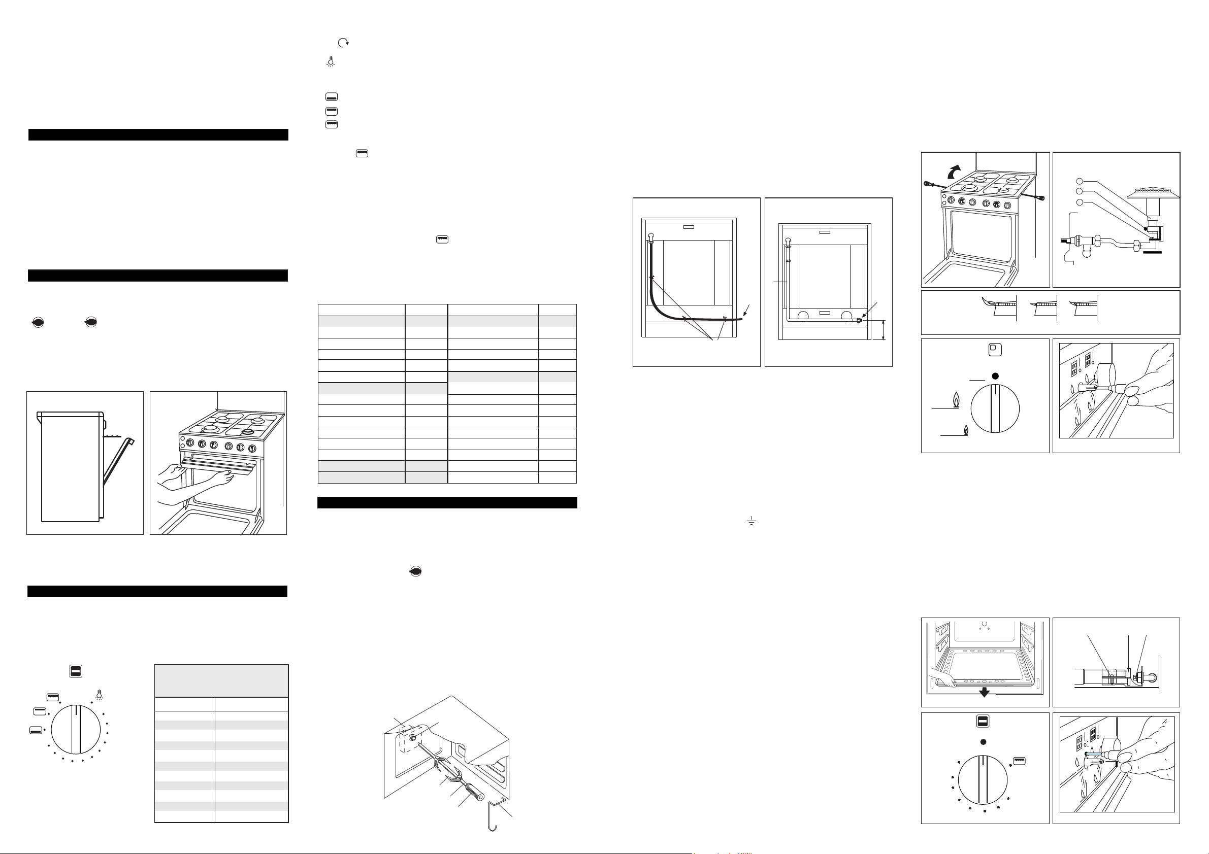
Pipe connection
Make the connection using an iron (R) or copper pipe (S) starting from attachment
C in (fig. 4). Remove hose attachment B using a 23 mm spanner. When making
the connection include an accessible ensure that the seal G is always placed between
the hose attachment and union C (fig. 4). When the connection is complete, always
check that there are no gas leaks from the union.
N.B. The connection between the end of the gas train and the supply can be made
on the right so that the gas pipe does not have to pass behind the cooker. In case
of connection on the left please relate to what already described in paragraph gas
connection having care to let the flexible tube pass through a holder see (fig. 5A)
in case of inflexible connection, see (fig. 5B).
170
B
A
8
1
2
3
4
5
6
7
BACK SIDE
Flexible tube entry
3) ELECTRICAL CONNECTION
The appliance belong to class "X" against fire dangers (see N.B par. 1).
Connection of the appliance to the power mains should be done by a licensed
electrician familiar with local safety regulations.
- This appliance must be earthed by law.
- Before connecting the appliance to the electrical supply, check that the earth
system in your house is working correctly.
- Check that unit voltage and power, marked on the rating plate applied on the
appliance, are correct for the supply;
- It is necessary that the feeding network is protected by a powerful switch able
to disconnect completely the network with a contacts separation of at least 3
mm.
Be sure that the earth wire green/yellow is not interrupted by the switch.
Important: The wires in the mains lead are so coloured:
- green/yellow = earth “ ”
- blue = neutral “N”
- brown = live “L”
- The supply cable must not come into contact with any component the temperature
of which exceeds the ambient temperature by 50°C;
- If a plug is used for connection, the plug to be connected to the supply cable
and the socket to which it is connected must be of the same type (conforming
to the standards).
- Easy access to the plug or the switch is ensured once the appliance is installed;
- Ensure that there is sufficient cable allowed for any subsequent removal of the
unit.
The manufacturer declines all responsibility for any damage to persons or things
caused by failure to observe the rules indicated above.
4) CONVERSION FOR DIFFERENT TYPES OF GAS
The cooker carries a label specifying the type of gas for which it has been preset.
If it is to be used with a different type of gas, convert as follows with:
— Replacement of the hose attachment as in the previous section "Gas connection"
— Replacement of the nozzles and air adjustment.
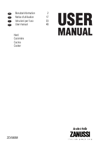
4a) Hob
The nozzles are replaced as described below:
— Disconnect the electricity supply plug if present and close the gas tap installed
upstream of the appliance.
— Remove the hob pan stands, flame caps and burner cups.
— With a screwdriver remove the two screws locking the hob, raise it up and
secure it to prevent from falling back down (see fig. 6)
— Remove the nozzle (2 fig. 7) and screw on the new one suitable for the new
gas type (see chart 1).
— Regulate the flame by backing off the screw (4 fig. 7). Raise or lower the pipe
(3 fig. 7). The best flame conditions are shown in (fig. 8) (regulate with
burners hot if possible).
— Reassemble all components, following the above sequence in reverse order.
— Low flame setting (olso for oven with thermometer)
To obtain this, set the knob in the position where the gas tap opening is
minimum (this position is indicated by a small flame screen-printed on to the
fascia in fig. 9). Slide the knob off and adjust the inside screw coaxial with the
rod of the gas tap (hole in the centre of the knob mounting rod, fig. 10).
Tighten or back off the screw until the flame is brought down to the level
required. This adjustment must be made with the burner on.
When using liquid gas this screw must be fully tightened. After making this
adjustment check that the burner remains on when switched rapidly from full
heat to minimum position and viceversa.
Fig. 5A Fig. 5B
BACK SIDE
Inflexible tube entry
3
4
2
NO NO YES
Fig. 6 Fig. 7
Fig. 8
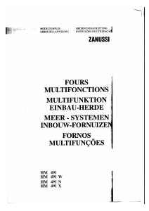
4b) Gas oven burner
— Remove the oven bottom (fig. 11).
— Unscrew the screws V (fig. 12) and remove the upper collar fixing the air muff
B (fig. 12) in order to have easier access to the nozzle.
— Remove the nozzle (F fig. 12) and screw on the one which is suitable for the
new type of gas (see chart 1).
— Regulate the flame by backing off the screws (V fig. 12) and move the pipe
(B fig. 12) backwards or forwards.
— Regulating the thermostat low flame position.
To do this, turn the oven to full heat (8) for about 10 minutes, then bring the
knob back to the minimum setting, position 1 (fig. 13). Remove the knob and
use the screw on the body of the thermostat (fig. 14) to set the flame size.
When using liquid gas this screw must be fully tightened.
After making this adjustment check that the burner remains on when switched
rapidly from full on to minimum position and viceversa.
Fig. 11 Fig. 12
Off
Max
Low
Fig. 9 Fig. 10
Fig. 11
Fig. 12
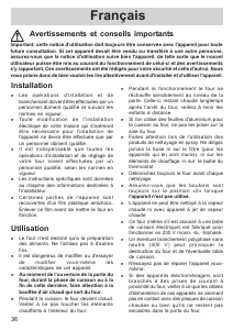
Pâtisseries
Il faut utiliser soit un moule à pâtisseries, la grille servant de support, soit la plaque
livrée avec l'appareil. Evitez de cuire deux gâteaux en même temps, ils seront réussis
s'ils sont cuits séparément. Pour les sablés: placer les biscuits sur la plaque à
pâtisserie à l'intérieur des deux lignes latérales en relief. Préchauffer au maximum
10 minutes: introduire la plaque et la grille de support sur le 3ème gradin du four
en partant du bas et à 2 cm à l'intérieur de la façade du four cuire indicativement
pour 16 minutes à la position 5 du thermostat. Eteindre et laisser reposer quelques
instants avant de retirer du four.
° C °C
VIANDES ENTREES ET LEGUMES
BOEUF ROTI 225-250 SOUFFLE 200
VEAU 250 TOMATES FARCIES 200
PORC 225 GRATIN DAUPHINOIS 200
MOUTON: GIGOT 225-270 PATE - TERRINE 200
EPAULE 225 PATISSERIE
VOLAILLES ET GIBIER PATE A CHOUX 200
POULET 225 FEUILLETEE 270
CANARD 225 SABLEE 200
OIE - DINDE 200-225 BRISEE 225
PINTADE - FAISAN 225 TARTES - QUICHES 250
PERDREAU 225 MERINGUES 100-150
LAPIN 200 FLAN - CLAFOUTIS 225
POISSON 200-225 BRIOCHE 225
CAKE 175-225 4 / 4 200
FOUR ELECTRIQUE A CONVECTION NATURELLE
Ce four est équipé de deux éléments chauffants (un dans la sole du four et l'autre
dans la voûte du four) qui peuvent marcher ou séparément ou en même temps
suivant la fonction choisie avec le sélecteur. (fig. 25).
Fig. 25
Tab. 3
Partant de la position 0 (ARRET) et tournant la manette du thermostat dans le
sens on assure successivement les opérations suivantes:
- Allumage de la lampe de four.
- 1-11 Repères chauffage de four (voûte et sole) et régulation de la température
de 50 à 250.
- Chauffage de la sole.
- Chauffage du grill moyen.
- Chauffage du grill fort.
Nota:
Le repère correspond également à la mise en route du moteur de
tournebroche (selon les modèles).
Cuisson au four
Préchauffer le four, pendant environs 20 minutes sur la position désirée, voir le
tableau (tab. 3). Enfourner la préparation à cuire. Couper le courant 5 à 10 minutes
avant la fin de la cuisson afin de bénéficier de la chaleur accumulée dans le four.
Cuisson au grilloir
Mettre la manette sur la position .
Avant d'enfourner, laisser chauffer 5 minutes porte fermée.
La porte du four doit toujours être entrouverte avec le déflecteur protége -
manettes en place comme indiqué dans la fig. 23-24.
Tableau indicatif d'utilisation du four électrique
Selon les modèles
Le grilloir peut être équipé d'une résistance électrique ou bien d'un brûleur à gaz.
Pour la mise en fonctionnement de la résistance électrique, répéter les opérations
décrites parag. GRILLOIR ELECTRIQUE ou FOUR ELECTRIQUE. Pour l'allumage
du brûleur à gaz répéter les opérations indiquées à parag. GRILLOIR A GAZ et
appuyer sur l'interrupteur .
Pour utiliser (voir fig. 26):
- Enfiler le poulet ou la pièce à rôtir sur la broche L en prenant bien soin de
l'immobiliser entre les deux fourches F et de bien l'équilibrer afin d'éviter des
efforts inutiles au moto-réducteur;
- Mettre la broche sur le support G, après avoir introduit son extrémité dans la
carré d'entraînement situé au fond du four P;
- Engager le plat lèchefrite sur le gradin inférieur;
- Mettre en place l'écran de protection de manettes (fig. 24)
- Mettre le moteur R en route et allumer le grilloir;
- Pour enlever la broche opérer de la façon contraire utilisant la manette S et un
gant de protection en laine isolante complet.
UTILISATION TOURNEBROCHE
S
L
F
R
P
G
Fig. 26
0
1
2
3
4
5
9
6
7
8
10
11
Allumage manuel du grilloir
Après avoir ouvert la porte du four, faire tourner la manette du four vers la droite
et la placer à la position grilloir (rectangle à droite fig. 21) et approcher une allumette
enflammée près des orifices du brûleur placé en haut du four.
Brûleur avec thermocouple de sécurité
Répéter les opérations ci-dessus, et en même temps presser sur la manette du four.
Quand l'allumage s'est produit, maintenir appuyée la manette pendant 10 secondes,
afin que le clapet de sécurité entre en fonction. Si la flamme devait s'éteindre une
fois que vous relâché la manette, recommencer l'opération comme décrite ci-dessus.
GRILLOIR A GAZ
GRILLOIR ELECTRIQUE
Fig. 23 Fig. 24
Selon les modèles
Certains cuisinière avec four à gaz peuvent être pourvues de grilloir électrique.
Pour la mise en fonctionnement de la résistance électrique presser le poussoir
; (le repère correspond également à la mise en route de moteur de
tournebroche s’il existe).
COMMENT UTILISER LE GRILLOIR A GAZ OU ELECTRIQUE
L'appareil est prévu pour griller à porte entre ouverte (fig. 23) avec la grille porte-
plats au troisième gradin en partant du fond du four, à 12 cm, à peu près de la
surface rayonnant et le déflecteur en place comme en Fig. 24.
L'utilisateur pourra changer de gradin, suivant son goût personnel et les nécessités
des différents mets.
Repère Température °C
1 50
2 70
3 90
4 110
5 130
6 150
7 170
8 190
9 210
10 230
11 250
Correspondance entre les repères
du thermostat et les températures
approximatives du four


Joignez-vous à la conversation sur ce produit
Ici, vous pouvez partager ce que vous pensez du Zanussi ZXT5050IE Cuisinière. Si vous avez une question, lisez d’abord attentivement le mode d’emploi. La demande d’un mode d’emploi peut être effectuée en utilisant notre formulaire de contact.