TF D01M 0001 SE 022551A0 230913
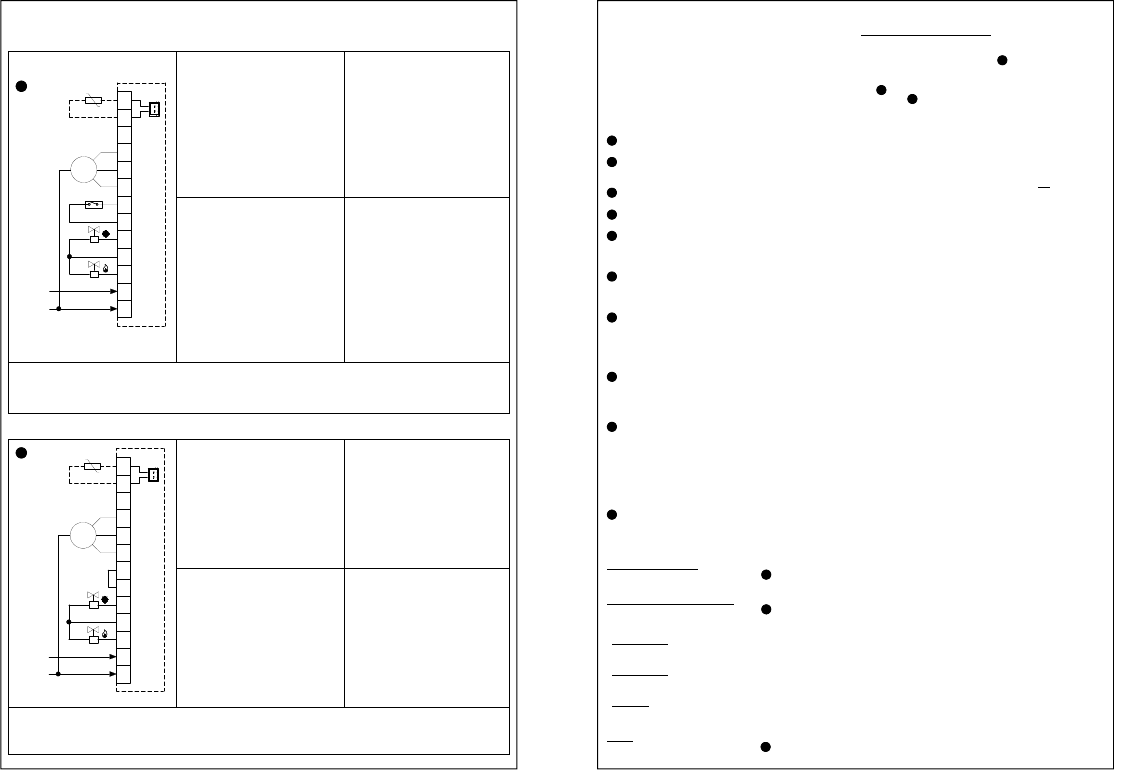
COLLEGAMENTI ELETTRICI / ELECTRICAL WIRINGS / ELEKTROANSCHLÜSSE / BRANCHEMENTS
ÉLECTRIQUES / CONEXIONES ELECTRICAS
MOTORE
Pos. ESTATE: Sempre acceso
Pos. OFF: Spento
Pos. INVERNO: Sempre acceso con
Termostato di mandata
MOTOR
Pos. SUM.: Alwais turned on
Pos. OFF: Turned off
Pos. WIN.: Always on, with termostat of
sent
ELETTROVALVOLE
Pos. ESTATE: E.V. freddo termostatata
Pos. OFF: Tutte spente
Pos. INVERNO: E.V. caldo termostatata
ELECTROVALVE
Pos. SUM.: E.V. cold termostat
Pos. OFF: All turned off
Pos. WIN.: E.V. heat thermostat
DISPOSITIVI CONTROLLATI
- N1 Motore a 3 velocità
- N2 Elettrovalvole
- Selezione Estate /inverno
- Termostato di mandata
CONTROLLED DEVICES
-N°1 3-speeds fan
-N°2 Electrovalves
-Summer/winter selection
-Termostat of sent
MOTOR
Pos. SOMMER: immer eingeschaltet
Pos. OFF: abgeschaltet
Pos. WINTER: immer mit
Förderleistungsther- mostat
eingeschaltet
MOTEUR
Pos. ÉTÉ : Toujours allumé
Pos. ARRÊT : Éteint
Pos. HIVER : Toujours allumé avec
thermostat de refoulement
ELEKTROVENTILE
Pos. SOMMER: zeitgesteuertes E.V. (Kälte)
Pos. OFF: alle E.V. abgeschaltet
Pos. WINTER: zeitgesteuertes E.V.
(Wärme)
ÉLECTROVANNES
Pos. ÉTÉ : E.V. pour froid thermostatée
Pos. ARRÊT : Toutes éteintes
Pos. HIVER : E.V. pour chaud thermostatée
GESTEUERTE GERÄTE
- N1 Dreigeschwindigkeitsmotor
- N2 Elektroventile
- Wahl Sommer/Winter
- Förderleistungsthermostat
DISPOSITIFS CONTRÔLÉS
- N1 Moteur à 3 vitesses
- N2 Électrovannes
- Sélection été/hiver
- Thermostat de refoulement
MOTOR
Pos. VERANO: Siempre encendido
Pos. OFF: Apagado
Pos. INVIERNO: Siempre encendido con
termostato de envio
ELECTROVALVULAS
Pos. VERANO: E.V. frío bajo control
Pos. OFF: Todas apagadas
Pos. INVIERNO: E.V. caliente bajo control
DISPOSITIVOS CONTROLADOS
- N1 Motor a 3 velocidades
- Selección Verano/Invierno
- N2 Electroválvulas
- Termostato de envio
MOTORE
Pos. ESTATE: Sempre acceso
Pos. OFF: Spento
Pos. INVERNO: Sempre acceso
MOTOR
Pos. SUM.: Alwais turned on
Pos. OFF: Turned off
Pos. WIN.: Alwais turned on
ELETTROVALVOLE
Pos. ESTATE: E.V. freddo termostatata
Pos. OFF: Tutte spente
Pos. INVERNO: E.V. caldo termostatata
ELECTROVALVE
Pos. SUM.: E.V. cold termostat
Pos. OFF: All turned off
Pos. WIN.: E.V. heat termostat
DISPOSITIVI CONTROLLATI
- N1 Motore a 3 velocità
- N2 Elettrovalvole
- Selezione Estate /inverno
CONTROLLED DEVICES
-N°1 3-speeds fan
-N°2 Electrovalves
-Summer/winter selection
MOTOR
Pos. SOMMER: immer eingeschaltet
Pos. OFF: abgeschaltet
Pos. WINTER: immer eingeschaltet
MOTEUR
Pos. ÉTÉ : Toujours allumé
Pos. ARRÊT : Éteint
Pos. HIVER : Toujours allumé
ELEKTROVENTILE
Pos. SOMMER: zeitgesteuertes E.V. (Kälte)
Pos. OFF: alle E.V. abgeschaltet
Pos. WINTER: zeitgesteuertes E.V.
(Wärme)
ÉLECTROVANNES
Pos. ÉTÉ : E.V. pour froid thermostatée
Pos. ARRÊT : Toutes éteintes
Pos. HIVER : E.V. pour chaud thermostatée
GESTEUERTE GERÄTE
- N1 Dreigeschwindigkeitsmotor
- N2 Elektroventile
- Wahl Sommer/Winter
DISPOSITIFS CONTRÔLÉS
- N1 Moteur à 3 vitesses
- N2 Électrovannes
- Sélection été/hiver
MOTOR
Pos. VERANO: Siempre encendido
Pos. OFF: Apagado
Pos. INVERNO: Siempre encendido
ELECTROVALVULAS
Pos. VERANO: E.V. frío bajo control
Pos. OFF: Todas apagadas
Pos. INVIERNO: E.V. caliente bajo control
DISPOSITIVOS CONTROLADOS
- N1 Motor a 3 velocidades
- Selección Verano/Invierno
- N2 Electroválvulas
4
A
4
N
3
L
50/60Hz
L
230V~
N
11
10
8
9
7
5
6
T.M.
M~
III
II
I
COM
E.V.
E.V.
12
13
S.A.
S.A.
N
L
4
3
5
III
7
6
8
M~
10
II
9
I
11
13
12
S.A.
S.A.
50/60Hz
L
230V~
N
COM
E.V.
E.V.
B
TF D01M 0001 SE 022551A0 230913
regulation will be performed, in the range +5°C .. +35°C.
KNOB ROTATION LIMITATION
It is possible to limit the rotation range for the set-poin knob by
following these steps:
1. Extract the knob as indicated in " " in the "INSTALLATION"
paragraph.
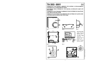
2. Position the mechanical pins as shown in the example in Fig. 6
( ). The field of rotation is, in this way, reduced as in the arc
shown in in Fig. 5.
THERMOSTAT OF SENT
The 'thermostat of sent' function is used to inhibit the fan
operation whenever, but only in heating mode, the supply water
is not hot enough.
For this function to operate it is mandatory to wire a sensor on
the delivery water pipe or, as an alternative and to the same
terminals, a bimetallic thermostat.
In the event that the thermostat of sent T.M. is not used it will be
necessary to apply a wire jumper between terminals 6 and 7.
INTERNAL / EXTERNAL SENSOR SELECTION
The thermostat leaves the factory already set for an internal
sensor work.
In those installations where a remote sensor is required, please
move jumper JP1 (located on the electronic board on the right
side of the selctors) into position A, as shown in Fig. 6, then
wire a 10KΩ @ 25°C NTC sensor with a proper 'Beta' value at
connector SA or, as an alternative, at terminals 12 and 13.
In case of doubts about the sensor to be connected, please ask
the producer.
TECHNICAL FEATURES
Power supply: 230V~ -15% +10% 50/60Hz
Power absorption: 3VA
Contact rating: 5 (1) A @ 250V~ SPDT
Sensor type: NTC 10KΩ @ 25°C ±1% int.
(remote optional)
Regulation range: 5°C .. 35°C
Accuracy: ± 1°C
Resolution: 1°C
Hysteresis: 0.5°C
Operating temperature: 0°C .. 40°C
Storage temperature: -10°C .. +50°C
Humidity limits: 20% .. 80% RH (non condensing)
Protection grade: IP 30
Case: Material: ABS self-extinguishing V0
Color: Signal white (RAL 9003)
Size: 132 x 87 x 37 mm (W x H x D)
Weight: ~265 g
a
WARNING
- To adjust properly room temperature, install the
thermostat far from heat sources, airstreams or
particularly cold walls (thermal bridges). When the remote
sensor is used in conjunction with the thermostat, then
this note must be applied to the remote sensor itself.
- For remote versions all wirings must be made using wires
with 1,5 mm² minimum cross section and not longer than
25 m. Do not use same duct for signal wires and mains.
- The appliance must be wired to the electric mains through
a switch capable of disconnecting all poles in compliance
with the current safety standards and with a contact
separation of at least 3 mm in all poles.
- Installation and electrical wirings of this appliance must
be made by qualified technicians and in compliance with
the current standards.
- Before wiring the appliance be sure to turn the mains
power off.
WARRANTY
In the view of a constant development of their products, the
manufacturer reserves the right for changing technical data and
features without prior notice. The consumer is guaranteed
against any lack of conformity according to the European
Directive 1999/44/EC as well as to the manufacturer’s document
about the warranty policy. The full text of warranty is available
on request from the seller.
OVERVIEW
This device is a thermostat intended for temperature regulation
in environments heated or cooled with fan-coil units. Power
supply is 230V~.
The device features an outlet to connect an external
temperature probe and another to connect a bimetal thermostat
for the "cutoff thermostat" function.
By means of the mechanical pins the angle of rotation of the
knob can be reduced.
INSTALLATION
Carry out the operations below to install the device, while
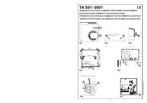
following the images on page 2:
Release the plate attached to the thermostat base by
pushing it to the left. This releases the teeth shown in Fig. 2.
Move both sliders all the way down and position the knob at
20°C; lift the knob using a screwdriver as shown by the
arrow in Fig. 3, being careful not to scratch the cover.
Push the plastic tab in the lower slot using a screwdriver,
slightly lifting the cover (Fig. 4).
Turn the cover, while pressing it slightly, until it is fully
extracted (Fig. 5).
Remove the mechanical pins from the thermostat base and
insert them in the cover to reduce the knob's field of rotation
(see example in Fig. 6 and read the "knob lock" paragraph).
The third pin at the top is a spare.
Fix the plate to the wall, using the two screw seats with centre
distances of 60 mm or 85 mm (use the supplied wall plugs
and/or screws). Pass the wires through the rectangular
openings.
-
Connect the thermostat base to the wall plate (pass the
wires through the rectangular openings). Align the base
holes with the special wall plate teeth, then press the base
to the left until the plate's plastic teeth click (Fig. 8).
-
Fix the thermostat base to the wall with the supplied
screws.
-
Make the electrical connections following the most
appropriate connection diagram (Pages 4, 5, 6 and 7).
-
Correctly set the connector JP1 if using a remote sensor.
See the "INTERNAL/EXTERNAL SENSOR SELECTION"
paragraph.
Perform the following operations to reclose the thermostat:
-
Position the two teeth from the top of the cover into the
specific slots and leave both sliders at the bottom.
-
Turn the cover making sure the sliders coincide with the
relative switches, push the plastic tab on the lower part of
the base inwardly (see the arrow in Fig. 7) and press it so
that the plastic fixing tab inside the special hole, at the
bottom of the cover, clicks. Check the sliders' correct
stroke.
Position the knob at 20°C and insert it on the cover.
OPERATION
The controls available on the front cover of the thermostat for
the user are two sliders and one knob.
3-SPEEDS SELECTOR
Through this three-position slide selector the user can choose
the (fixed) speed of the fan-coil motor.
COOL / OFF / HEAT SELECTOR
Through this three-position slide selector the user can choose
the operating mode of the thermostat as in the following
explained:
- Cooling Mode:
Set the slider to the position with the symbol n
nn
n: cooling mode
is then selected.
- Heating Mode:
Set the slider to the position with the symbol f
ff
f: heating mode
is then selected.
- Off Mode:
Set the slider to the position with the symbol 0: the thermostat
is turned off.
KNOB
Through the temperature set-point knob the user can set the
temperature desired in the room, according to which the
- ENGLISH -
1
2
7
4
6
5
3
8
9
2
E
A
B
10
C
F
9


Joignez-vous à la conversation sur ce produit
Ici, vous pouvez partager ce que vous pensez du Seitron TFD01M0001SE Thermostat. Si vous avez une question, lisez d’abord attentivement le mode d’emploi. La demande d’un mode d’emploi peut être effectuée en utilisant notre formulaire de contact.